Master Juniper JN0-664 Exam with Reliable Practice Questions
You must alter class-of-service values in packets on the outbound interface of an edge router.
In this scenario, which CoS component allows you to accomplish this task?
Correct : C
Class of Service (CoS) in networking is used to manage traffic by classifying, scheduling, and sometimes modifying packets to ensure network performance and Quality of Service (QoS). Different CoS components are used to achieve these goals. Let's analyze each option to determine which CoS component allows you to alter class-of-service values on the outbound interface of an edge router.
1. **Output Policer**:
- Policing is used to control the rate of traffic sent to or from a network interface. It can drop or remark traffic that exceeds a certain rate.
- Policing is not typically used to alter CoS values but to enforce traffic limits.
2. **Scheduler**:
- A scheduler is responsible for managing the order in which packets are transmitted out of an interface based on their CoS markings. It can allocate bandwidth and prioritize traffic.
- The scheduler manages how packets are queued and sent but does not alter the CoS values of packets.
3. **Rewrite Rules**:
- Rewrite rules are used to modify the CoS values of packets, such as DSCP (Differentiated Services Code Point) or 802.1p bits, as they exit an interface.
- Rewrite rules can alter the class-of-service values in the packet headers to match the desired policies of the outbound interface.
- Therefore, rewrite rules are the correct component for altering CoS values on an outbound interface.
4. **Forwarding Classes**:
- Forwarding classes are used to categorize packets into different traffic classes within a router for QoS handling.
- They help in defining how packets should be treated by the scheduler but do not directly modify the CoS values.
**Conclusion**:
To alter class-of-service values in packets on the outbound interface of an edge router, the correct CoS component to use is:
**C. rewrite rules**
**Reference**:
- Juniper Networks Documentation on CoS: [Class of Service Overview](https://www.juniper.net/documentation/en_US/junos/topics/concept/class-of-service-overview.html)
- Junos OS CoS Configuration Guide: [Rewrite Rules](https://www.juniper.net/documentation/en_US/junos/topics/topic-map/class-of-service-rewrite-rules.html)
Start a Discussions
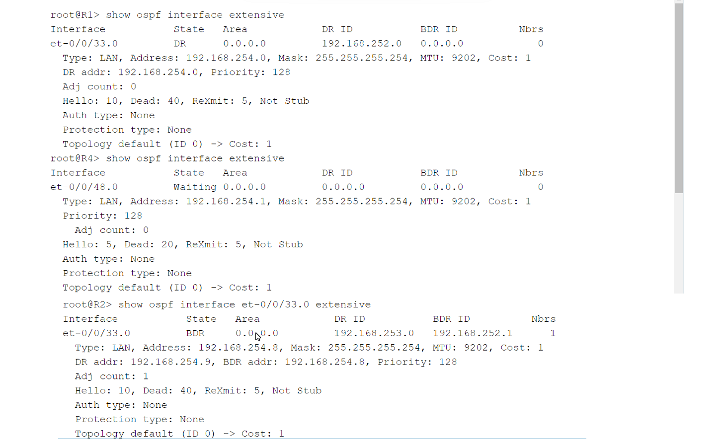
Refer to the exhibit.

Click the Exhibit button.
You have an OSPF environment. You have recently added a router called R4 that is directly connected to R1 and R2. You discover that R4 is only peering with R2.
Referring to the exhibit, how would you correct the peering?
Correct : C
In OSPF, routers form adjacencies by exchanging Hello packets. These packets contain several parameters that must match between OSPF neighbors to establish a successful adjacency. Key among these parameters are the Hello Interval and the Dead Interval.
Let's analyze the exhibit and the question to determine the correct course of action to ensure that R4 peers with both R1 and R2.
1. **OSPF Hello and Dead Intervals**:
- **Hello Interval**: The time in seconds between Hello packets sent out by a router. Default is usually 10 seconds for broadcast and point-to-point networks.
- **Dead Interval**: The time in seconds that a router will wait to receive a Hello packet from a neighbor before declaring the neighbor down. Default is usually four times the Hello Interval (40 seconds).
2. **Analysis of the Exhibit**:
- **R1's Interface**: Shows a Dead Interval of 40 seconds.
- **R2's Interface**: Shows a Dead Interval of 40 seconds.
- **R4's Interface**: Shows a Dead Interval of 20 seconds.
From the exhibit, we can see that R4 has a Dead Interval of 20 seconds, while R1 and R2 have Dead Intervals of 40 seconds. This discrepancy prevents R4 from establishing an OSPF peering with R1.
3. **Option Analysis**:
- **A. Adjust the Priority on R1 to be lower than the Priority on R4**:
- Incorrect. The OSPF Priority is used for DR/BDR election on multi-access networks and does not impact peering issues.
- **B. Change the MTU size on R1 and R2 to be 22 bytes higher than R4's MTU size**:
- Incorrect. While MTU mismatches can prevent OSPF adjacencies, the exhibit does not indicate an MTU mismatch issue.
- **C. Adjust the Dead Interval on R4 to match the Dead Interval on R1 and R2**:
- Correct. Matching the Dead Interval on R4 to 40 seconds will ensure that all routers have consistent Hello and Dead Intervals, allowing OSPF adjacencies to form.
- **D. Adjust the Hello Interval on R1 and R2 to match the Hello Interval on R4**:
- While this would be a valid approach if the Hello Intervals were mismatched, the exhibit shows that the Hello Intervals are consistent (10 seconds) across all routers. Therefore, this adjustment is not necessary.
**Conclusion**:
To correct the OSPF peering issue, the Dead Interval on R4 should be adjusted to match the Dead Intervals on R1 and R2. The correct answer is:
**C. Adjust the Dead Interval on R4 to match the Dead Interval on R1 and R2.**
**Reference**:
- Juniper Networks Documentation on OSPF: [OSPF Overview](https://www.juniper.net/documentation/en_US/junos/topics/concept/ospf-routing-overview.html)
- OSPF Configuration Guide: [Configuring OSPF](https://www.juniper.net/documentation/en_US/junos/topics/task/configuration/ospf-configuring.html)
Start a Discussions
A router running IS-IS is configured with an ISO address of 49.0001.00a0.c96b.c490.00.
Which part of this address is the system ID?
Correct : A
In IS-IS (Intermediate System to Intermediate System) routing, each router is identified by a unique ISO (International Organization for Standardization) address, also known as a Network Entity Title (NET). The NET consists of three parts:
1. **Area Identifier**: Indicates the area to which the router belongs.
2. **System Identifier**: Uniquely identifies the router within the area.
3. **NSAP Selector (NSEL)**: Typically set to 00 for a router, indicating the Network Service Access Point.
The format of the ISO address is `49.XXXX.YYYY.YYYY.ZZZZ.ZZZZ.00`, where:
- `49` is the AFI (Authority and Format Identifier) indicating a private address.
- `XXXX` is the Area Identifier.
- `YYYY.YYYY.YYYY` is the System Identifier.
- `ZZZZ.ZZZZ` is the NSAP Selector.
Given the address `49.0001.00a0.c96b.c490.00`:
- **Area Identifier**: `49.0001`
- **System Identifier**: `00a0.c96b.c490`
- **NSAP Selector**: `00`
**Explanation**:
- **A. 00a0.c96b.c490 is the system identifier**:
- Correct. The System Identifier in an ISO address is a 48-bit (6-byte) field used to uniquely identify the router. In this address, `00a0.c96b.c490` is the correct 6-byte System Identifier.
- **B. 0001.00a0.c96b.c490 is the system identifier**:
- Incorrect. This includes the Area Identifier as part of the System Identifier, which is not correct.
- **C. c96b.c490 is the system identifier**:
- Incorrect. This is only part of the System Identifier. The full System Identifier must be 6 bytes long.
- **D. c490 is the system identifier**:
- Incorrect. This is an incomplete and incorrect part of the System Identifier.
**Conclusion**:
The correct part of the address that represents the System Identifier is:
**A. 00a0.c96b.c490 is the system identifier.**
**Reference**:
- Juniper Networks Documentation on IS-IS: [IS-IS Configuration](https://www.juniper.net/documentation/en_US/junos/topics/task/configuration/isis-configuring.html)
- ISO/IEC 10589, the IS-IS routing protocol standard.
Start a Discussions
You are using a Layer 3 VPN to connect two customer sites. The VPN routes for the customer networks appear as hidden in the bgp. 13vpn. o routing table on the PE routers.
What is causing this problem?
Correct : B
For a Layer 3 VPN to function correctly, an MPLS Label Switched Path (LSP) must be established between the Provider Edge (PE) routers. The MPLS LSP is necessary for the transport of VPN traffic across the service provider's backbone network. If the MPLS LSP is not established, the PE routers cannot forward the VPN traffic properly, causing the routes to be hidden in the BGP routing table.
Here's a breakdown of why the other options are less likely:
A . The routes use overlapping IP addresses.
Overlapping IP addresses might cause issues with route advertisement and selection, but they would not typically cause routes to be hidden in the bgp.l3vpn.0 table.
C . There is a routing loop in the service provider backbone.
While routing loops are problematic, they would not specifically cause the routes to be hidden in the bgp.l3vpn.0 table. Routing loops would more likely result in dropped packets or increased latency.
D . Route targets are not configured.
Incorrect or missing route target configuration would prevent routes from being imported into the correct VRF, but it would not usually result in the routes being hidden. Instead, they would simply not appear in the relevant VRF.
Thus, the absence of an established MPLS LSP is the most plausible cause for the routes being hidden.
Start a Discussions
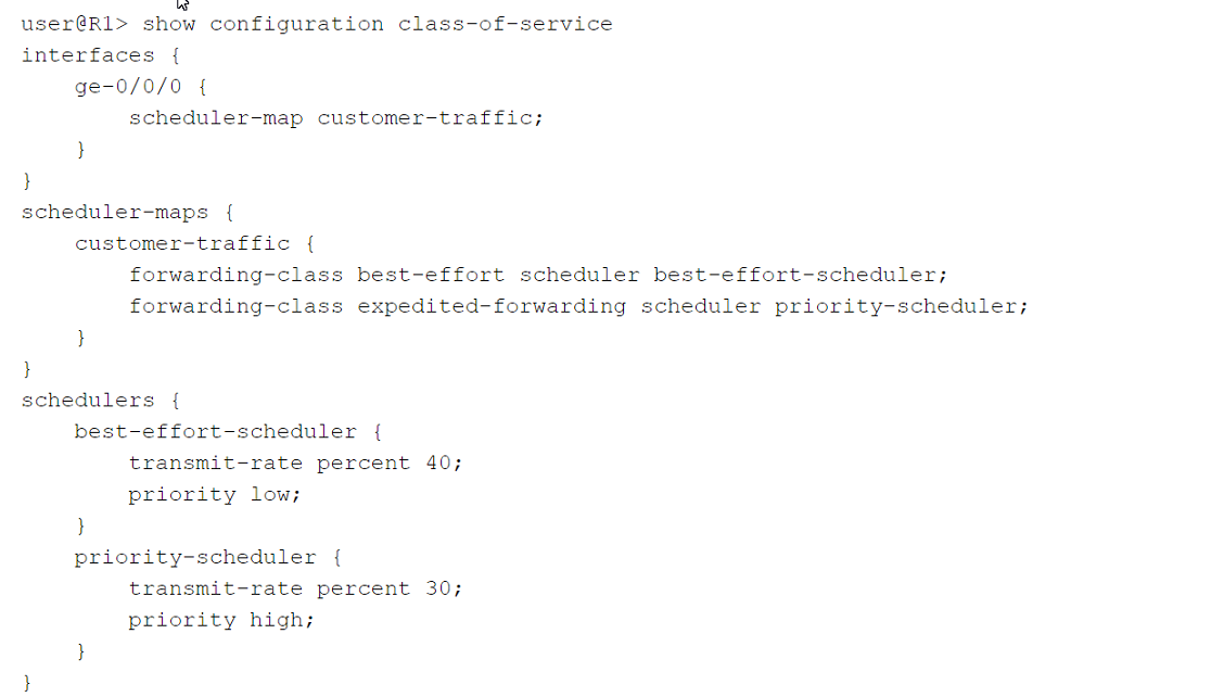
Refer to the exhibit.

Click the Exhibit button.
Which two statements are correct about the class-of-service configuration shown in the exhibit? (Choose two.)
Correct : A, B
The class-of-service (CoS) configuration in the exhibit shows how traffic is scheduled on the ge-0/0/0 interface. Let's analyze each statement to determine its correctness:
A . Incoming traffic will not be classified because no classifier exists in the configuration.
This statement is correct. The configuration shown does not include any classifier, so no explicit classification is defined. As a result, incoming traffic will not be classified according to any custom criteria.
B . The best-effort queue can transmit more than 40% of the total bandwidth on the ge-0/0/0 interface, if no other queue is using that bandwidth.
This statement is correct. The transmit-rate percent 40 means that 40% of the bandwidth is guaranteed for the best-effort queue, but it can use more bandwidth if other queues (like the priority scheduler) are not utilizing their allocated bandwidth.
C . Incoming traffic will be classified using the default classifier.
This statement is incorrect. Without an explicit classifier in the configuration, there is no mention of a default classifier being used. Therefore, the incoming traffic won't be classified based on the configuration shown.
D . The best-effort queue can never transmit more than 40% of the total bandwidth on the ge-0/0/0 interface, even if that bandwidth is available.
This statement is incorrect. The transmit-rate percent 40 sets a guaranteed minimum bandwidth but does not set a maximum limit. The best-effort queue can utilize more bandwidth if other queues are not using their allocated portions.
Start a Discussions